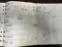
I have a 95 VK540 that I was given, but there was no wiring harness, just a motor in a chassis. I'm trying to wire it just to get spark. I have a manual with the schematic, but my brain just isn't computing the wires. Anyone here able to tell me which wires need to be connected to get spark across the plugs. TIA!!!
Attachments
does it still have a stator on the motor?
is cdi box still with chassis?
is cdi box still with chassis?
Yes stator is still on the motor.does it still have a stator on the motor?
is cdi box still with chassis?
I have a spare CDI from another VK
I also have spare coil from another VK
Plugs coming from stator and CDI are there, its just there is no wires/harness in between them. Wire from CDI to coil is self explanatory. I am wanting to patch from the stator to the CDI to get the system to spark. So that's eliminating ignition switch, TORS and all. I just want to get it sparking, lighting coil and ignition shut off not necessary at this time. But as I said, I can't make heads or tails out of the diagram that's in the manual in front of me.
Last edited:
eep, i can follow them but i need time to sit and will admit i am better with the actual harness in front of me. i might have a harness less the e start in a few weeks from an 88 as i am working on a deal on a scrapped one for the engine for another guy and i am getting the e start for my 88 from it.
Got it sparking, running is yet to happen, but here is what I did.
STATOR---------------------------CDI-------------------------COIL
W/R--------------------------------W/R
Y-----------------------------------Not used (lighting coil)
B-----------------------------------Ground
W----------------------------------B/Y (will be switched)
R-----------------------------------R
Br----------------------------------Br
____________________________O----------------------------------O
**On a side note, either the yellow or white wires coming from the stator will energize the system to spark by connecting to the Black/yellow wire of the CDI. I think what I will do is. Use the White wire coming from the stator to power the system and send that through a switch to the Black/Yellow wire of the CDI, then when this circuit is broken it will shut the engine down. Might not be right but at this point in time that's what works.
Last edited:
Got it sparking, running is yet to happen, but here is what I did.
STATOR---------------------------CDI-------------------------COIL
W/R--------------------------------W/R
Y-----------------------------------Not used (lighting coil)
B-----------------------------------Ground
W----------------------------------B/Y (will be switched)
R-----------------------------------R
Br----------------------------------Br
___________________________________O----------------------------O
**On a side note, either the yellow or white wires coming from the stator will energize the system to spark by connecting to the Black/yellow wire of the CDI. I think what I will do is. Use the White wire coming from the stator to power the system and send that through a switch to the Black/Yellow wire of the CDI, then when this circuit is broken it will shut the engine down. Might not be right but at this point in time that's what works.
I believe Black should go to Black yellow.
White is coming off charging coil and is used to charge battery I think.
I'll give that a try and find out what happens.I believe Black should go to Black yellow.
White is coming off charging coil and is used to charge battery I think.
RON HYDRAULIC YAM
Member
Too cold to go out and look at my 93? VK
i have a 8AU-28197-JO manual , not sure age but it shows
At the key ..black short to blk/whte to shut off
Stator has a wh/red join to cdi unit
red just heads off to lights
brown to cdi and to blk/wh at key switch.
.
cdi has bl/yl to throttle switch and tors
.
orange from cdi to coil..other side of that coil in scmatic to ground
opposite side of coil shows one end to each plug..
.
the brown also goes to eng stop sw and tether...
..
my humble conclusion ... ground the stator , wht/red to cdi , brown to cdi , red to cdi
orange to coil
ground the coil ?... only other thing shows TOR is a normally grounded switch but expect
it works unplugged as mine is.
..
the blk / yel on cdi may work disconnected...
.
the white in this book is just a charging wire to rectifier and onward.
the red wire also wanders off into the grip warmer sys as well as cdi
...
and after all that . my book was published july 92. AND i'm just old and not as experienced
as fellows like Maim,, just following wires in schematic...
.
I hope these extra parts are from same machine .
Good luck.
great old sled . does everything but steer... all that track pushes the sled straight unless
the ski carbide can grad solid ice or snow.
Ron
NorthofSixty
Active member
BY is normally the TORS and needs to be grounded BY-B to bypass the throttle and carb switches. White should be the charging coil for the battery and can be left disconnected. There should also be a BW from the cdi that is for the kill and key switches. BW-B to shut off the engine. Make sure the black wire from the stator is connected to the black from the CDI and to the chassis ground.


