Build a virtual pinball machine. I have some plans from the internet to use 3 monitors. The playfield will be a 46" super thin LCD tv with the end being the bottom or towards you. Not 100% sure of the other sizes(I have it saved on my computer somewhere). You can have as many games on it you want! I have about 20 on my pc now working.
I am getting the hang of the software. Gotta have something to go with the arcade machine and dart machine!
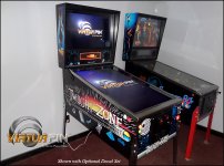
It will look similar to this:
I am getting the hang of the software. Gotta have something to go with the arcade machine and dart machine!
It will look similar to this:
Attachments
Last edited:
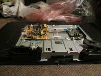
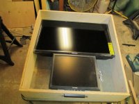
Now gathering the materials needed. Have the monitors and cabinet grade 3/4" plywood sheets. 46" playfield, 32" backglass, and 17" DMD. I may go with a real DMD if I can save in other areas. No pics worth taking yet. Have real work coming in finally so only work done was decasing the 46" tv.
Will look something like this with different artwork. Actually kind of like the Twilight Zone theme.
Will look something like this with different artwork. Actually kind of like the Twilight Zone theme.
Attachments
Last edited:
tippmannator
New member
Neet! Gotta add wifi /blutooth so we can all take a crack at the high score lol
you would enjoy Instructibles website
devinzz1
Active member
Neet! Gotta add wifi /blutooth so we can all take a crack at the high score lol
^^^ this
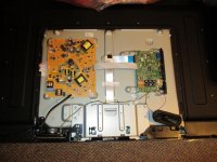
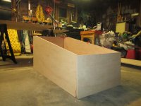
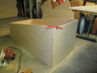
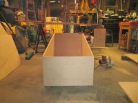
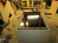
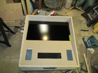
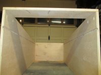
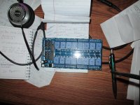
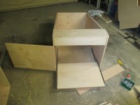
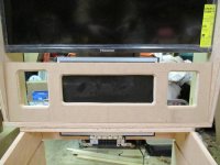
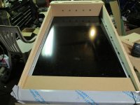
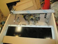
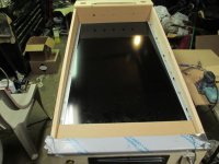
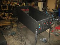
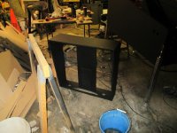
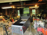
Gonna have to check it out. The motherboard I am using has wifi built in. Got some progress but had to modify the plans quite a bit because the tv wouldn't completely de-case so I had to widen it about an inch. The plans are for a standard Williams widebody machine. I will route 9mm deep x 1cm tall groves on the inside of each side to slide the tv in. A hinged back door on base and backbox. I still have to modify those plans to fit a 32" with a 17" monitor right below it. All kinds of lighting effects also and some real pinball mechanisms for sound and force feed back. I may put a score motor and reels inside for the sound of the old EM tables. The EM(electro-mechanical) tables are more complex to set up to make things happen at a certain time. On the newer ss(solid state) machines, it a little easier because they run off the actual rom chip from the original machine. The ems didn't have a rom so I hear you have to mess with the scripts in the main program. As far as electronics, so far I have a 16 channel relay board 12v 30a to run some higher draw things(shaker motor, knocker, ect) a 12v switching power supply. Some older em parts(sling shots, ect). For everything else there is a usb board that uses the rom program to send signals to this board(ledwiz) and a booster board which I don't have yet because the guy said to wait until midweek and he will have a new board thats better then all previous boards. So, I haven't seen anything from him(zebsboards.com) to run all the special effect strobes and RGB's which I never knew about. They are LED strips or individual LEDS that change colors by vari-ing the voltage, never heard of that but sounds neat. I still have to get the hardware kit(legs chrome trim, glass channels, ect), a coin door, digital plunger kit, lit buttons, a bunch of stuff. I was going to go on ebay tonight but its too late. Heres what I got so far: (not much) Tomorrow, mod the plans for the backbox and start cutting that. This is just a test fit and it sure would be nice if I could find the other 3 corner clamps. I do have some strap style clamps. I just hope I can get the tv high enough so the flipper buttons go in the correct place. All this messing around because I was too cheap to buy the tv that works perfectly without modding the plans, but I saved $200. That also means that I have to get a lockdown bar custom made for the width. It's a project that has all kinds of hidden costs. I don't even know where I am going to put it. Ahhh, who needs a dresser. Nothing like tearing apart a brand new tv. For a $400 46" tv, this thing has some very good viewing angles and it remembers its last state of power when unplugged. Its all going to run off my old PC with a few upgrades(video card and memory) got a used video card for $115 shipped($200 new). The memory is cheap.It has 2 Gb and I think 6 Gb should do it.
Attachments
Last edited:
Just bookmarked that industructabls website, neat stuff there! I don't think this would qualify because it's a "real" hobby with forums and specialty store sites.
Wasn't sure of their rules. They do give a ways for different projects to be submitted. Another one is Make Magazine, they are more electronic oriented and do alot of publishing of books for people to do projects and understand computers, programing and electronics in general(that is where I am, first book)
I have seen one of theses done on instructibles but was done as a coffee table, glass top and you could play games through it. As a kid there used to be one at the pizza place we used to go to.
great project, will be following for sure.
I have seen one of theses done on instructibles but was done as a coffee table, glass top and you could play games through it. As a kid there used to be one at the pizza place we used to go to.
great project, will be following for sure.
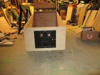
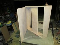
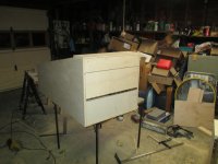
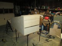
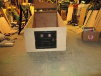
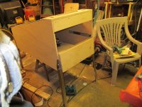
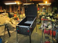
Got quite a bit of progress. Screwed up a few times, had to remake the rear of cab(I forgot about the legs). All tv's fit and seems to be going ok except my parts order still hasn't shipped. Sounds familiar. here are some of the latest pics:
Attachments
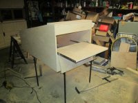
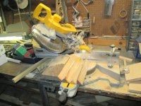
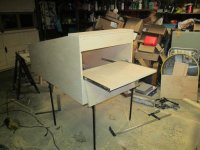
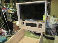
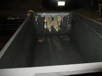
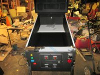
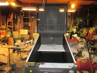
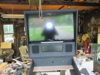
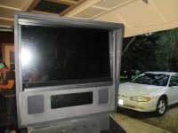
The pics are all out of order but you can see how it's going. The playfield tv slides in those routed slots after I took the case off. Got some toys for it already and alot still on the way. I am going to have 11 12v solenoids placed in various locations for force feedback from flippers, pop bumpers, slingshots, and 1 replay knocker. Lots of LEDs. I have 300-5meter strip of standard RGB leds and 2 1 meter strips of what they call WS2812 RGB LEDs(60 per meter). Those last ones can be controlled individually with a pc board called an Arduino. Still learning this part. The other leds can change color by changing what thay call PWM (pulse width modulation)supposedly you can get like 100000 different colors on each LED seperatly. I was too cheap to buy a real booster board so I am using that 16 channel relay board is what is going to control the solenoids. Still got more to order but as usual,went over budget already. 2 output controller boards are on order. That saw pic is making corner braces but that wood is too knotty and I don't have the hardware kit yet so I don't know what size to make them for the leg mounts. Real Williams legs, all stainless trim, sweet! I might redo that bezel for the top box, it looks kinda cheesy. It's 1/4" hard board, I was going to run the router around it but may scrap that idea a do something else. That pic with the playfield tv looks like the tv is tilted the wrong way, I had to measure it and its actually 4 1/2" higher in the back then front.(the 4:02am post). I think I saw that coffee table one. The fold down door hides a tray, thats where the motherboard is going and most PC related stuff. Too much to do yet.
My sleds are not put away yet, still waiting for that fluke snowstorm. LOL
I have the base cab on a card table because those $25 plastic saw horses collapsed under the weight of 1 4x8x 3/4 sheet of plywood, actually I had the wood on them and tried to slide it and snap. 1 still is useable.
Can't lay out the buttons, don't have them yet. I know the round ones are 1 3/8 hole for them but the rectangular ones, not sure about.
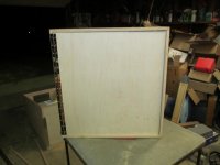
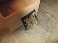
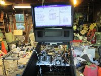
Thats it for now. All or most screws are pocket screwes so no filling and sanding. 2 are visible, I can't see them in the pic but its the 3rd pic in my first post today with the backbox with monitors in. the last pic on this post is the old back doo setup. I wonder how the legs would fit? lol
Attachments
Last edited:
Re-did some things. Modified backbox so it wasn't so huge, redid the back door(forgot about the legs!). Gathered the pc components, ordered electronics from ebay and other sources. I do just a little at a time. Got my MRI Monday, FINALLY!
Still waiting for the cab hardware, should ship next week.(legs, stainless trim, buttons, custom lockdown bar)Starting to really get held up by this. A few more pics:
Backbox looks normal now. That is my 3rd speaker/DMD panel, no mater what I do, I still get waves but it's better then the old one. New pc pullout tray. Those drawer glides are horrible so I got new ones today, the ones that suck the drawer closed when it gets to a certain point. "H" channel sits on speaker panel and then plexi. Mask the screen view on plexi and paint everything else so you dont see the bottom of tv or that gap. Of all the pinballs I looked at, that panel is a little more then 25% of the total front so thats what I came up with. The problem is now I cant fold the top forward but top has to come off anyway to fit in all the doorways.
Attachments
Last edited:
Starting to work on it again. Broke my drill battery but not going to sit around moping anymore.
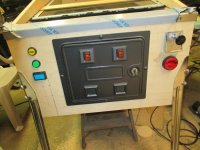
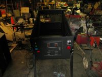
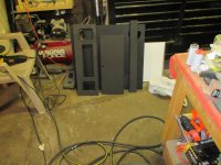
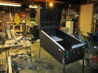
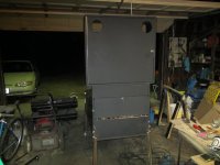
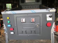
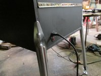
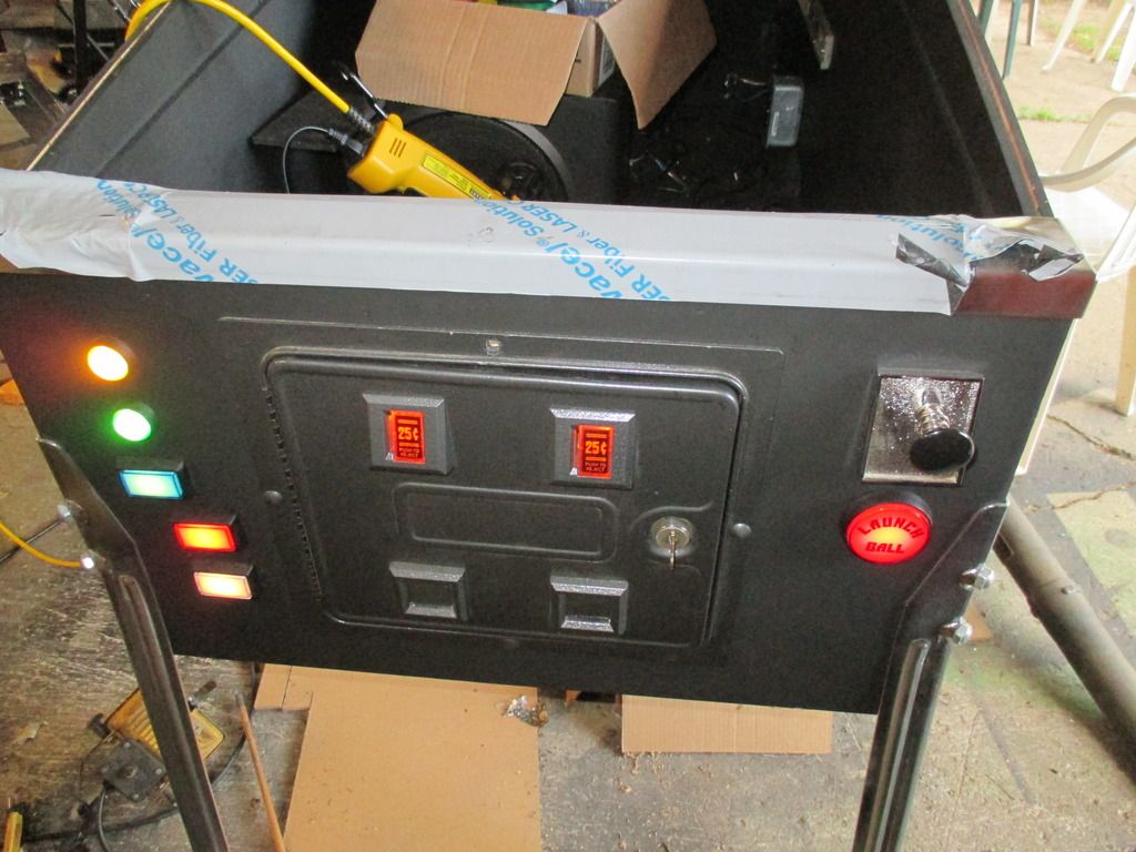
Making headway but still a long way to go. Got the hardware kit finally and put the legs on and the lockdown bar just tonight as a matter of fact. Coin door is mounted and a few buttons. Not sure how many I want on it. I want enough to doo all functions but not over do it so it looks like a hand full of Skittles. I just made and put the corner braces between the leg braces and legs. I could not find my wood glue so I had to use construction adhesive and had to work fash as it sets up hast so I drilled one hole a little off and took forever to get bolt started but tightened it in time. Still gotta do the rear leg corner braces. Ppl on that forum were always asking why I wanted to put wood in the corners because it is very hard to bend the brackets. Not trus, about 10lb ft and they would bend. Still a lot to do yet but a little at a time. That panel with 5 holes in it will be my home made flasher panel with a strobe at each end. 12v choked down to 5v 350Ma 1 watt RGB LEDs. I will have the same on the back for a kind of light show on the wall behind it but unsure is I will but it inside with holes for each light or on the outside. I have all kind of neat LEDs for this but if you like cool LEDs, youtube "drean lights". I need some of those just for decoration. I didn't peel that protective coating off the lockdown bar, just peeked, nice brushed stainless steel. I have all the trim except for what goes around backbox. Not sure what I am going to do there. I think I skipped a few steps from last update until now. Let me know how many buttons would be ok. The green is credit in and the launch ball button is for machines that didnt use a plunger (T2, ect) I have quite a few more buttons, all lit.
Attachments
Last edited:
Here are some progress pics, it's slowly coming together. Way humid to paint today but did anyway, with both hands numb from those magic shots, and I gotta get more 6/15. The legs were all condensed and sawdust stuck all over them but I think it's coming together. I went to fire up the pc components and they fire up but nothing, no beeps or anything. This is a liquid cooled processor and the first time I fired it up, one of the hoses broke and got coolant on the motherboard but let it sit a long tome and its dry so I must be overlooking something, I noticed the hard drive wasn't even spooling up so thats 12v and not the mobo. Yeah I gotta be overlooking something or maybe it doesn't agree with the other memory chips I put in and no onboard speaker for beep codes so I will see if I can dig one up one of these days. I just hope I don't have to buy a new pc for this. I am sure this is fine but we'll see. Starting to look like a pinball. Not sure if I like the off set button, that why there is only 1 on it, to see if I like it. I could put buttons on the bottom and not totally sure how many I need. Thats the inside view so you can see the leg bracket in the way. The paint was still tacky an hour ago and I put this coat on at about 7pm. I'll hopefully have more done tomorrow. I am test fitting everything so the whole thing will be sorta together soon.
Attachments
Last edited:
Worked on pinball cab most of the day with the test fit. Everything seems to be ok. Just not sure if I like that offset button on lower left. It's starting to look like a pinball cab now. I may actually have a job tomorrow so after that I will try to install the backbox monitors. I may have to reverse the backbox lock because if the key is left in, it likes to unlock and swing open.
Attachments
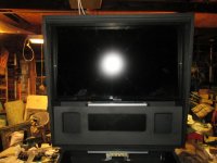
Got the backbox monitors on. This will be covered in plexiglass with the edges painted from the inside to hide everything but the screen.
I won't do it but wouldn't a Darth Viper theme be nice?
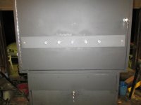
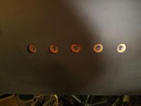
The 2 pics with the 5 holes are the rear flashers, the inside holes are 1 1/2" for heatsinks. They are 1 watt RGB LEDs and should put a nice light show on the wall behind it.
I won't do it but wouldn't a Darth Viper theme be nice?
The 2 pics with the 5 holes are the rear flashers, the inside holes are 1 1/2" for heatsinks. They are 1 watt RGB LEDs and should put a nice light show on the wall behind it.
Attachments
So I put 1 more button on the front and bought some speaker cloth. I got a gift card from amazon for my Z-906 speakers headphone jack becoming loose. I probably did it myself but I usually crank the headphones and when it cuts out from wiggling the plug, the speakers come on for a loud blast. I cant figure out how to take the control panel apart yet but haven't spent much time on it. I got 83 bucks worth of free stuff from amazon because of this. So I ordered a new motherboard, a 3/32 slot cutting router bit, and the power input jack for the back. Should all be here around 2pm Thursday. Then I can finally do something besides sitting on a lawn chair all day. Hey, still gotta exchange those tracks. I get more shots Monday but I thing those will be fine. I bought an outlet box and outlet, and faceplate for the input thing. I don't know what it looks like on the inside. Anyone building a project, be wary of Menards plywood. I have a feeling this router bit is going to flake out the core but we'll see. The router bit is for a grove that plastic trim that holds the glass in is for. WOW are those little rgb led flashers bright, still seeing spots.
Attachments
Last edited:
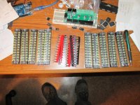
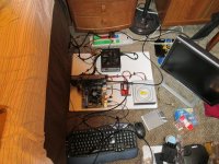
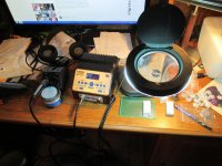
I had to build a new pc for this thing and used a solid state hard drive, wouldn't believe it if I didn't see it how fast those are and this one is a cheapo. Boot time to windows 7 ultimate from not even plugged in is 5 seconds, ready to use. But this is for a pinball so doesn't matter as much. I got my soldering station for building the resistor boards fot the flashers and the pc prototype boards so ready to go on that. Got the back glass installed and the trim but needs a little touching up, I have an extra piece of extrusion so may cut some pieces off and use them to fill the gaps. So we got the pc built with OS and most pinball programs, still had to buy an adaptor from VGA to DVI D. Just the way the videocard is. Enough text, time for pics.....The pics are out of order because when I uploaded the from the camera, I must have opened a different destination folder because thats why they are all screwed up. 1 is the plug-in thing I boutgt and installed a 15A outlet inside the cab, 1 is the soldering station ready to go but not now, put it away, 1 is the cut plexi in place with the trim on but it needs some more work, not sure what the 4th one is, I will have to arrange pics by the number to get them in order. Oh, 1 is the PC all assembled on that white slide out drawer, the SSD is right next to the cd drive which could probably come out because it was there to install the OS from a disk, all other software can be installed from a flash drive. Screen is all ditry and finger printed but nothing like my laptop, I put 2 nice scratches in the screen a few hours ago. I put it away so I didn't have to see them.
Attachments
Last edited:
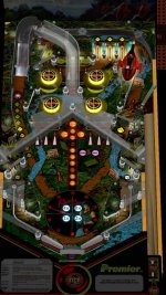
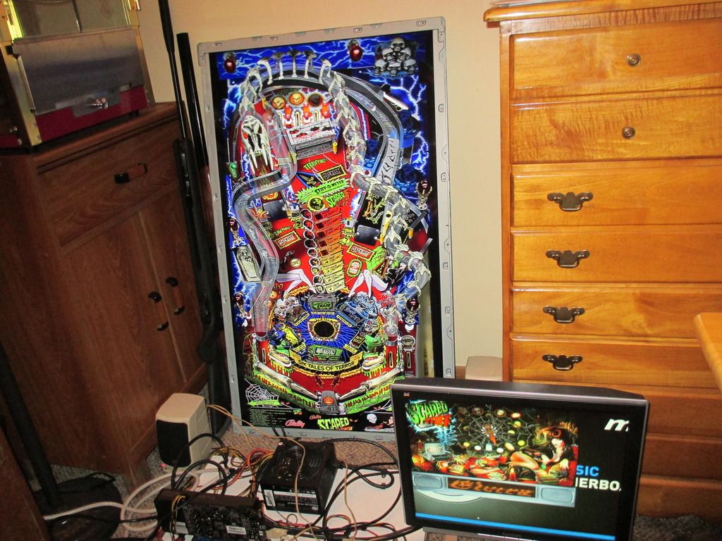
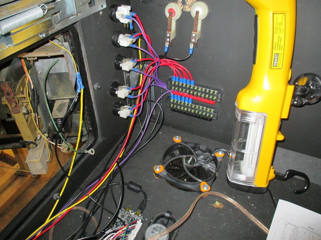
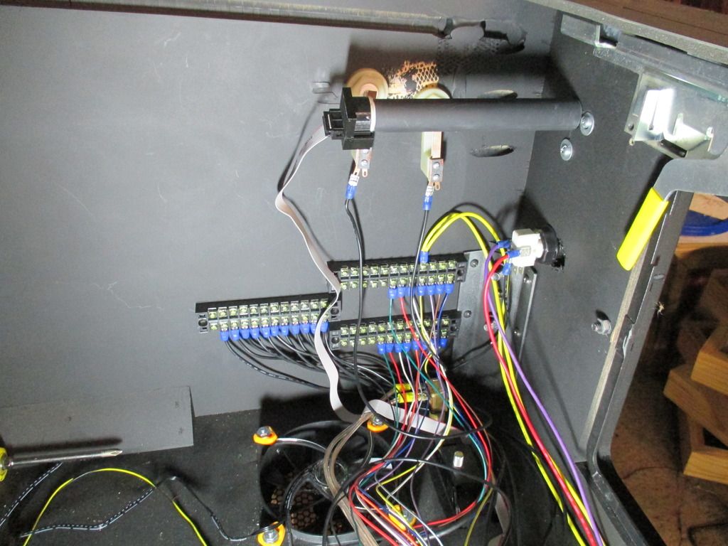
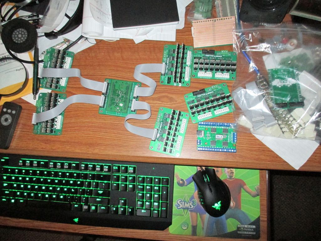
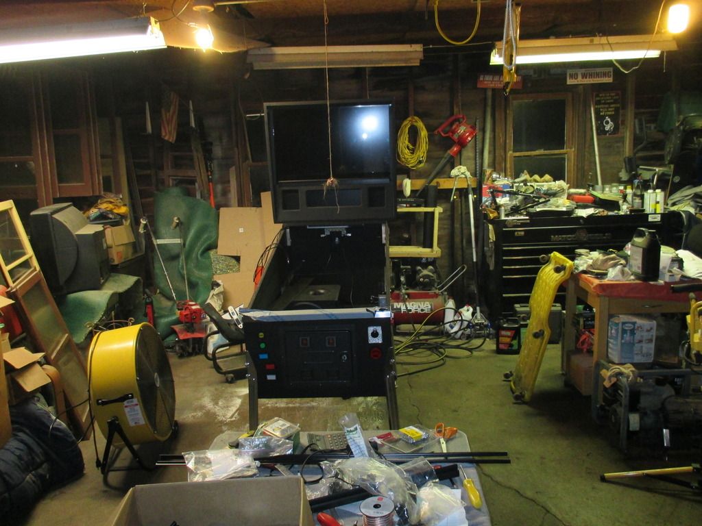
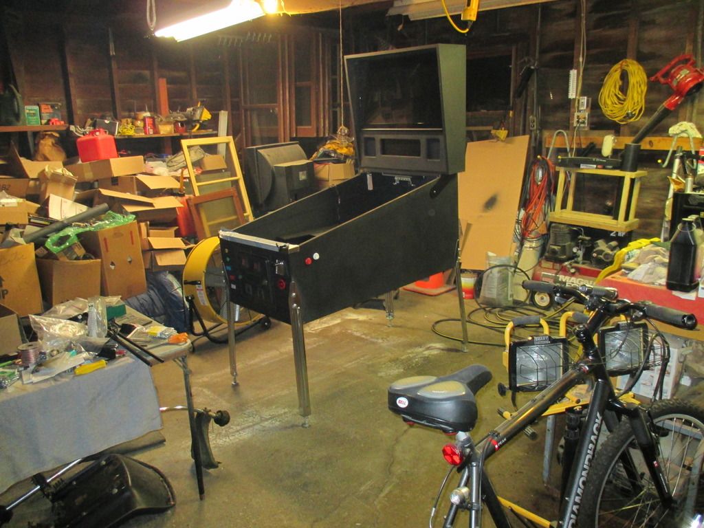
I have some more progress on the virtual pinball. My biggest struggle it the visual basic this is all programmed in. HOLY COW! I didn't expect the cost and more pc knowledge. I have all the control boards for a total of 96 outputs for forcefeedback and lighting effects. I will include a few videos which are kind of the same but more detail on the 2nd one. Here is a screen shoot of Scared Stiff featuring Elvira on my test setup. I will also include some wiring pics. This thing is going to have more copper in it the wood!
I am uploading a vid so I am not sure if I can add the ones I mentioned.
Anyone really good with visual basic, let me know. I am having trouble programming the PC
https://youtu.be/0pgXn_i88h8
https://youtu.be/0CQV5bRTrZk
I want to put all that stuff it it but this thing is begining to take up too much time.
Later....,
Vic
I am uploading a vid so I am not sure if I can add the ones I mentioned.


Anyone really good with visual basic, let me know. I am having trouble programming the PC
https://youtu.be/0pgXn_i88h8
https://youtu.be/0CQV5bRTrZk
I want to put all that stuff it it but this thing is begining to take up too much time.
Later....,
Vic
