I'm having some issues with the power valves on my 98 SRX 700 and as I took them out to inspect and troubleshoot them I had several questions.
In trying to better understand how the power valves work here are some of the questions that I have:
1a) When the servo motor actuates (pulls back the valves) what determines how far the servo motor shaft turns, thus how far the cables are pulled? Are there internal switches within the servo motor?
1b) Same question as 1a accept on when the servo motor unwinds and allows the valves to spring back into the exhaust what determines when the servo motor stops?
2) I believe I've read that it is a common problem for the cables to pull out from the valve and that there are people or shops out there that will replace the end of the valve where the cable attaches. Stock this part of the valve is aluminum and these aftermarket people/shops replace that end either with carbon steel or stainless steel. I read Hauck Power Sports does this and if I'm not mistaken it sounded like they use carbon steel. Then I read about somebody who is active (or used to be active) on this Totallyamaha forum who used stainless steel. Anybody know if this person is still around and still doing this mod for people?
3) I've seen some youtube videos for adjusting the power valves. The person used two 2.5 mm allen wrenches to adjust the cables/valves properly. Somebody else commented that may be a bit tight and 3 mm wrenches may be better. Thoughts on 2.5 vs 3 mm wrenches to use? Also, in the video it was mentioned that if you turn the idle down below 900 rpm the servo motor does something. What does the servo motor due when the idle is lowered below 900 rpm? What/where do I adjust to change the idle? I assume it must be on the carb.
4) This one is theoretical. Does anybody know how the SRX 700 engine would run with the power valves in the full open position all the time? I'm a big fan of the KISS principle (Keep it simple stupid) and I'm just curious. I'm thinking like connect the valve to a blank plate that bolts up to the cylinder such that the valve is inserted but in the full open position all the time, thus eliminating the complexity of the servo motor and cables. Would this engine be really poor in the lower rpm range with the valves full open? Would there be any jetting concerns in the lower rpm range since you are essentially changing the exhaust resistance/back pressure. Part of me says I'm OK with a bit of reduced power/efficiency at lower rpms. If I really want to go I'm going to give it enough throttle to get rpms above where the power valves would open anyhow.
5) What rpm are the power valves supposed to open up at?
I think that's it for now. Sorry for the long and wordy post and some of the newbie type questions. Any thoughts/answers you may have regarding these questions would be much appreciated. Happy Sledding!
1a) The cdi and rpm determine when and how much the servo opens
1b) I believe there's a stop inside the servo motor to tell it when to stop unwinding the cable spool.
2) There are still a few guys around that fix the powervalve ends and the most common fix is to use a stainless bolt vs carbon steel.Hauck Powersports does it plus a few others.
3) 2.5 mm is the general rule of thumb and is also the Yamaha spec.I have a U shaped shim that slides down over the valve and that makes the job easier not having to hold 2 allen wrenches in place and adjust the cables.
Turning the engine down to 900 opens the servo up to the full open position allowing you to mark the spot so if it moves while your making the cable adjustments you can move it back.This method is used if you don't have the service cable for doing the slack adjustment.
Holding the valves in the full open position will kill your bottom end and the engine will work sluggish,
5) until it gets to around 65-7000 where the valves are supposed to open.
fourbarrel,
Thanks for the info. I will have to try and contact some of the posters on this site who were fixing power valves, at least several years ago they were based on all the posts I read. I do have one more question that came about after I removed my power valves and completely disassembled and cleaned them. I just have to figure out how to post a picture to better explain the question/situation. Is there any instructions available for attaching pictures to a thread?
Thanks for the info. I will have to try and contact some of the posters on this site who were fixing power valves, at least several years ago they were based on all the posts I read. I do have one more question that came about after I removed my power valves and completely disassembled and cleaned them. I just have to figure out how to post a picture to better explain the question/situation. Is there any instructions available for attaching pictures to a thread?
A couple of bucks
VIP Member
A couple of bucks
VIP Member
In the tool bar just above where you type at the far r/h side, there is aIs there any instructions available for attaching pictures to a thread?
Quote bubble
Just to the left of it there is a film or video
And finally next to that there is a picture. Click on it.
OK. I see the the little picture icon left of the video icon and I click on it. Then I clicked "Choose Files" and find my picture and click it. It's a ".jpg" file. When I then click "Upload File(s)" I get an "Upload of file failed" message. I assume this is where the problem is. Has anybody else experienced this problem when trying to attach a picture file?
I'm still having trouble posting a picture so I will state my new power valve question below. If I ever figure out how to get my pictures attached I will do so as they sure do make it easier to understand what I have and what my question is.
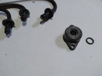
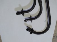
So I recently removed the power valves from my 98 SRX700. Two of the PVs had suffered the dreaded cable pull through failure and the third one looked OK. After removing them I completely disassembled them and cleaned them all up. When cleaning everything up I noticed something strange. One of the three cables is different than the other two. The difference is right where the cable goes into the valve housing (Holder 3 on the Yamaha parts diagram). On two of the three cables there is a groove machined into the cable jacket about ⅛” from a second groove which is for the circlip. It would appear to me that this groove is for an o-ring. However, on the third cable jacket this second groove does not exist, only the circlip groove. Furthermore, on the valve housing (Holder 3) there is a machined groove on the end where the cable enters. It would appear that is also for an o-ring. Looking at the Yamaha parts diagram there is only one o-ring and it goes into this groove on the end of the valve housing (Holder 3). See attached pictures showing this detail.
So I am confused. Why the difference between the cable ends? Is this 0-ring groove by the circlip groove supposed to exist? Are there two o-rings associated with the cables? Has anyone else seen this discrepancy?
Thanks for any insight you may have.
A couple of bucks
VIP Member
I have. If I go into my pictures and crop them .... I cannot post them.Has anybody else experienced this problem when trying to attach a picture file?
mod-it
Member
Pics could be too big as well, a resizer is needed. It will only allow pics up to a certain size. I believe 800x800 is near max size but will work.
Alright. It looks like I finally got a picture to post. As you can see and as I mentioned a few responses ago two of the three cable ends have a second groove just back from the circlip groove but the third cable does not. Any thoughts on this? Should that groove be in all three? Is that groove for an o-ring? The Yamaha parts diagram only seems to show an o=ring that goes between the disc looking piece of the cable end and the housing the cable goes through. Here is a pick of the housing.


